

Parameter Chart
Perhaps the most indispensable piece of documentation provided with the Chroma was the parameter chart. This is a guide that lists each possible value for every parameter that makes up a Chroma patch, plus some additional diagnostic commands. It is available here in various formats. These include the fixes mentioned in Chroma Notes.
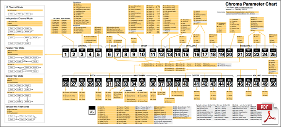
New Parameter Chart
The parameter chart has been rethought by Chris Ryan [21030691] with the goal of improving readability and utility. Changes include:
- explicit representation of modulation selections from Pitch, Wave Shape, Cutoff, and Volume to Glide, Sweep, and Envelopes 1 and 2;
- differentiation of parameters and functions not available in a stock Chroma or Expander (use of grey colour);
- comprehensive list of Set Split commands;
- comprehensive list of Syntech and CPU Plus (CC+) panel parameters;
- additional information for some parameters;
- redrawn Patch [1] routings;
- elimination of heavy black borders around all the parameters;
- use of mixed case, which is easier to read than all caps;
- executed in OmniGraffle, much easier than Illustrator—and resulting in a smaller PDF (98K vs. 1.2MB).
- parameterchart2.1.pdf (64K)
See discussion threads New Parameter Chart, March 2009; and New Parameter Chart Update, January 2010. For a list of changes in version 2.1, see Parameter Chart Version 2.1, February 2013.
Original Parameter Chart
This original PDF version of the parameter chart is no longer maintained, but will be retained here for convenience and as an historical record. It was redrawn by Chris Ryan [21030691] based on the original (below) and contains some updated information but not all of the corrections and comprehensive listings of the current version above.
- parameterchart.pdf (64K)
- parameterchart.xls (111K Microsoft Excel spreadsheet by Sandro Traversi [21010217])
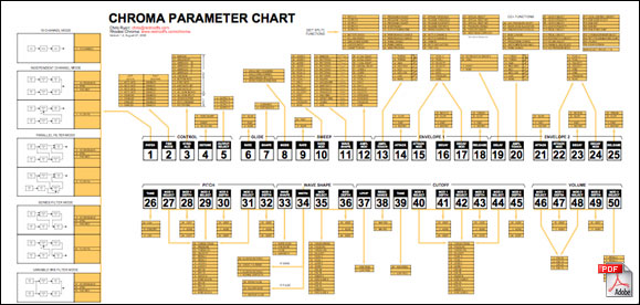
Version 1.2 adds CPU Plus (CC+) functions; thanks to Åke Danielson [21010068] for providing this update. Version 1.1 adds [SET SPLIT] commands 31-35. David Clarke [21030085++] provided the following information:
Set Split 31 is discussed in "Section 4. Diagnostics" of the Service Manual. AUTO TUNE and [SET SPLIT] [50] will end up doing the same sort of "Reset"/"Tune" whereby bad boards are ignored and board assignment is descending (opposite from [SET SPLIT] [31]).
The presence/details of [SET SPLIT] [32] and [SET SPLIT] [33] came from my review of the firmware code.
There are really two pairs of Functions, AUTO TUNE with [SET SPLIT] [31] and [SET SPLIT] [32] with [SET SPLIT] [33].
The first one of each pair (AUTO TUNE & [SET SPLIT] [32]) will 'do their thing' (tuning in their own way), and will remove any failing boards. The board assignment will be that of the power-on board (i.e., descending).
The second of each pair ([SET SPLIT] [31] and [SET SPLIT] [33]) does the same type of tuning as their counterparts from the first part of the pair; however, they allow all boards to be used (whether they failed or not) - and board order is ascending.
I've now just gone back and re-reviewed SET SPLIT 32 and SET SPLIT 33, and there looks to be limited use there for Joe Average. It appears that these will attempt to scale the timer readings for a "1MHz emulation mode." I can only imagine that this would have use to the development team - as I don't know what it would do for us ...
We have:
- Set Split 31 = Normal Tune, Ascending - don't kill bad boards
- Set Split 32 = "1MHz emulation mode" tune, Descending - kill bad boards
- Set Split 33 = "1MHz emulation mode" tune, Ascending- don't kill bad boards
- Set Split 50 = Normal Tune, Descending - kill bad boards
SET SPLIT 34 and SET SPLIT 35 are the front-panel equivalents of the "Pressure Switch Off" and "Pressure Switch On" messages outlined for the Chroma interface in the Chroma Computer Interface Manual (ref: Opcodes 14 and 15), so the comments there correctly describe what SET SPLIT 34/35 will do.
Scan
Thanks to Eric W. Mattei [21030443+], here is a high quality scan of the original paper parameter chart (click for full size):

This includes a sticker noting that two of the Parameter 1 diagrams were reversed in the original printing.
Parameter Sheet
As a last resort for storing patches—if you don't have either a MIDI interface and a computer or a cassette player and/or can't get the cassette interface working—this paper-and-pencil parameter sheet should do the trick.
Download and print, then enter the patch parameter values manually. ![]()