

Test Controller
By Luca Sasdelli [21010226]See also Luca's follow-up post in January 2012.

First of all: it works.
In the last few years I’ve had several dual voice boards (DVB) to repair, and to use a genuine Chroma as a test bench isn’t a good idea: plug and unplug, switch on and off and back on ... all tasks that can impact on an old instrument, even potentially damaging it in several ways.
Moreover, the diagnosis of DVB faults on the Chroma isn’t that easy, because of the auto-tune software that drives the voice boards in a proper manner, forcing the engineer to take counter-measures to understand what the fault is.
The late David Hillel Wilson's Voice Board Test Controller documentation is unfortunately limited to the control panel, the schematic diagram and a few waveforms; there no assembly details at all (except for the case).
I planned the Test Controller several months ago and began to think about how to assemble one; here are my relevant items:
- there are quite simple logic and analog parts, to be assembled on standard stripboards
- most of the logic board is straight connected to the DVB pins, so multiple cable etc.
- the four 8-pin connectors for the DVB are unevenly spaced, in respect to the standard stripboard holes: connectors P5 and P6 are OK, same for P7 and P8, but between P6 and P7 the board holes don’t match
- the control switch diode matrix is prone to assembly errors
- the 24 LEDs run with the on-board clock (about 500Hz), so their indication isn’t that useful in my opinion
- almost one half of the Test Controller is made of wires (yikes!)
Circuit description
Although the original schematic is quite easy to understand, here a brief explanation of the Test Controller circuitry.
In order to test a DVB, the required waveforms and control voltages have to be generated in a way that the board understands them. A clock generator (CD4001 quad NOR gate used with some feedback to oscillate) runs at about 500Hz and provides all the required signals; the clock pulse goes into an Address Generator (CD4024) that encodes the serial clock in a 0-to-7 sequence on a 3-bit internal bus: the generated pulses perform the following tasks:
- the three-bits sequence is decoded by the CD4051 (8-way analog multiplexer, widely used on the Chroma itself) to read voltages from eight potentiometers, and presents them as multiplexed values on the Analog Input (“DAC”) of the DVB
- they create the Sample and Hold control buses (SHA0, SHA1, SHA2), that will decode the multiplexed analog voltages of the previous point
- the third purpose is to drive the control matrix via the CD4028 (BCD-to-decimal decoder), by issuing both the Strobe signals (-STB0, -STB1, -STB2) and the “drive” bank select signals, allowing the diode matrix to get each single switch state, to being sent it via the CD4050 hex inverting amplifier and from here to the DVB data bus. The DVB will decode the data and will feed the proper logic state to the various analog switches and signals on the board.
Yes: it’s all here. This bunch of components allow proper analog voltage generation and feeding, as well as all needed switch logic states to route the DVB signals across the various paths. In conclusion, it can test each DVB component.
Other components are a very simple audio inverting buffer (TL071), the noise circuitry and a very basic linear power supply.
Planning
The idea to build it on a single PCB was soon discarded: the DVB connectors part is mechanically stressed by tests and brings 32 wires with it, including power, so I decided to assemble the DVB socket and the logic part on a single stripboard; moreover, the rotary switches are a bit difficult to find and they can have different pinouts and spacings. The original prototype has the DVB connectors fixed on top of the case, but this requires a more PCB and relevant wiring, so I preferred to keep the assembly as neat as possible.
Color-coded wires are widely used to avoid easy mistakes. Molex KK-series connectors are also widely used to allow easy maintenance and faultfinding. All ICs are mounted on high-quality sockets, to avoid damage during soldering (heat, static).

Components
The parts are as follows:
- main board (clock, logic, DVB connectors)
- diode matrix (hardwired BCD-encoder)
- front panel with manual controls
- power supply + audio buffer
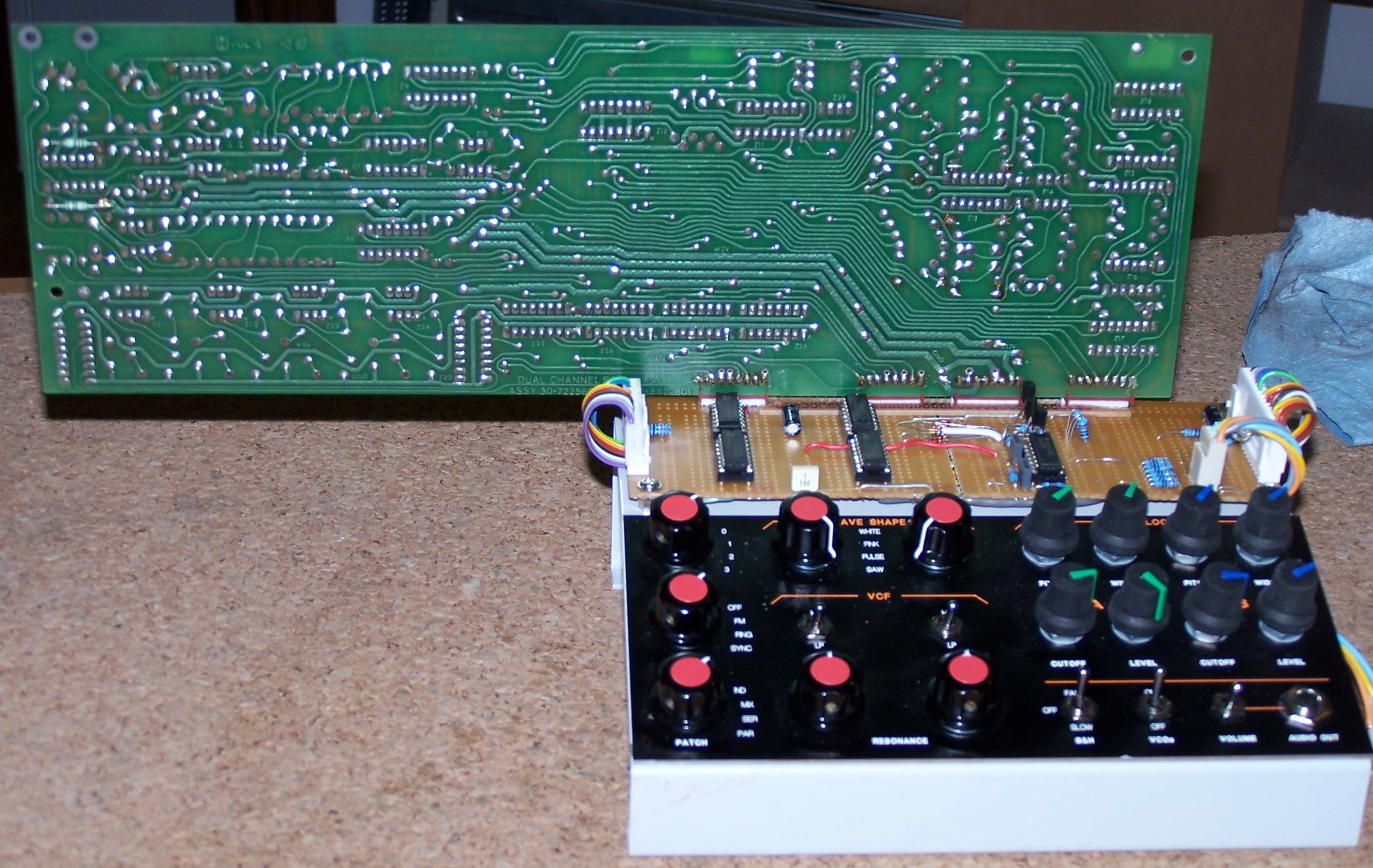
Main Board
To mate the unevenly spaced DVB connectors, I did split a stripboard and re-assembled it with the correct spacing, then enforcing the assembly with some glued bars for mechanical stability.
The two half boards are dedicated to relevant DVB connections: the left with logic counters and the right with clock, power, noise generator and analog output buses.

The noise generator is copied from the ARP Odyssey 2823 generator using a zener diode; the Pink noise LPF is the one from the Test Controller schematics; the noise generation has the only purpose to check that the respective audio paths are working as expected, so any kind of sound generator should work.
The mainboard is wired using soldered wire-wrap connections: this kind of wire is extremely thin, strong and the sleeving insulator is quite safe from overheating, avoiding short circuits due to soldering iron accidental contacts.

Diode Matrix

The diode matrix is made as a totally passive stripboard, connecting the diodes in a BCD- encoding logic: from here, a 6-bit bus goes to the CD4050 hex inverting amplifier; the controls are linked using Molex KK-series connectors.

The switch and diode matrix is distributed with this logic: I found it very useful to make the matrix board.
Front Panel
I’m definitely not a brave bricoleur, so I decided to plan a front panel to be created by a dedicated service (Schaeffer AG): within the design, I’ve used the original one, grouping the controls in order to follow some interconnections standards and tried to keep the panel text as low and short as possible, to lower the costs! :)

- DVBtesterorgonblkbordato.fpd (Front Panel Express file, 2K)
Then, the (thin!) front panel was used as a guide to make the corresponding holes in the case panel, coupling them to make a quite solid support for all manual controls. All switches and potentiometers are kept in place with respective alignment pins, thus avoiding unwanted rotations with use.
Power Supply
The power supply is pretty straightforward: I’ve used a sealed transformer to limit event of some shorts inside the case; the +5V regulator is the one with the highest power dissipation (7V voltage drop) and therefore it has the biggest heatsink. The rectifier capacitors are perhaps too big in respect with the current drain, but I’ve preferred to stay on large values for safe working; some small capacitors (220uF) are on the mainboard to lower the power impedance. The audio buffer is on the same board, because the wire should come straight from the Output selector, instead of going back to the mainboard and from here down to the amp.

Case
I’ve chosen a very small one: indeed it could be easier to work with a larger box. Simply I didn’t want big tools around, because my room is very small: this is the only reason in choosing it.
Considerations
Some cons: this toy is expensive, much more than I initially expected. Some of the components are hard to find and sometimes I had to agree to pay quite high prices for them; maybe some money could be saved by developing full-logic switches instead of mechanical ones. Due to its particular structure, the assembly is a quite long task, and is error-prone.
The usage is limited only to those technicians faced with several Chroma repairs; I’ve built it simply because I don’t want my Chroma ruined by performing too many tests on it.
Now the pros: it makes the DVB feel like a duophonic analog synth, so it’s very comfortable to follow the signal and identify the bad components. The logic offers some reference waveforms, so the timing is easy to see even without a logic analyzer.
Possible improvements
- reference voltages to check regular range of VCO and VCF (e.g. min-max)
- a PCB grouping together logic, noise, diode matrix, audio and power supply would make the assembly lot easier and error-free; there is still the DVB connector matter
- a semi-automatic and/or stepped test sequence, to be sure having tested all DVB features
- logic control via membrane keyboard (why not?), or via computer, even including the above point 3.
