

Expander Performance Manual: Hookup
The Expander is designed to operate on either 120V AC or 240V AC (50-60Hz.). Check the serial number plate on the rear of the instrument for its power setting. If the voltage setting is incorrect, your local service center can easily change it using an internal switch. Be sure the LOCK/UNLOCK switch (located on the rear of the instrument) is in the LOCK position before powering the Expander to prevent accidental loss of programs. Connect the power cord to the power jack on the rear of the Expander, and plug the power cord into a grounded three prong outlet. To reduce the chance of grounding problems, use the same power circuit as your amplifier.
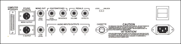
Connect your amplifier to either the XLR-type MONO OUTPUT connector (one of the STUDIO OUTPUTS), or the quarter-inch MONO OUT jack (either HIGH LEVEL or LOW LEVEL, whichever works best for your amplifier). Or the Expander's audio can be mixed with the Chroma's by using a stereo phone to phone cable that has been wired like the diagram. Connect this from the Expander's HIGH LEVEL MONO OUT jack to the Chroma's AUDIO INPUTS/OUTPUTS 0 jack. (Expander tip to Chroma ring.)

Connecting and using the foot switches and pedals will be discussed later in this manual [see Performance Controls: PEDAL Inputs]. Connect the 25 pin cable to the COMPUTER INTERFACE jacks on the Chroma and the Expander. The cable is reversible so either end can go to either system. Secure the cable ends with the hardware.
When the Expander's power switch is first turned on, the LEDs (Light Emitting Diodes) will all blink rapidly. During this time, the Expander is going through its initialization and tuning program. When the circuits are tuned and tested, the PROGRAM NUMBER display will light up with a program number. (If the small DATA READOUT shows "Err" followed by numbers, it means an error has been detected. See the Diagnostics section for more details.) Initialize the interface by pressing [SET SPLIT] [17] on the Chroma. Now the Chroma keyboard will control the Expander.
Then, center the MONO OUT EQ sliders and raise the VOLUME slider. Then check that the LED over the Program Select Switch ([PROG SELECT]) is lit. Depress [PROG SELECT] if it is not lit.

The Expander is now ready to use. By pressing any of the fifty numbered switches on the right control panel, you can use the program stored at that location. All 50 of the programs stored in the Expander's memory can be used in this manner. A listing of the programs is included with this manual. The Expander generates and uses radio frequency energy. If it is not set up and used according to this owner's manual, it may cause interference to radio and TV reception.
The Expander has been tested and complies with the limits for a Class A computing device in accordance with the specifications outlined in Sub-part J of Part 15 of the FCC Rules and Regulations. These rules are designed to provide reasonable protection against interference in a commercial, non-residential area. There is, however, no guarantee that interference will not occur in a particular installation.
To determine whether the Expander is causing interference, turn it off and observe any change in the interference pattern. If the Expander is causing the interference, move the TV or radio antenna until the interference stops.
Computer Interface
The Expander is also designed to be controlled by an external computer. Complete information on the hardware and software needed for computer interfaces can be found on the Chroma Interface Manual.